Are Smart Vents Safe? A StaticPressure and 2026 Analysis
Decide whether retrofit smart registers can correct a hot or cold room without restricting required HVAC airflow. Includes baseline tests, closure limits, failsafe controls, and acceptance checks.
Direct Answer
Decide whether retrofit smart registers can correct a hot or cold room without restricting required HVAC airflow. Includes baseline tests, closure limits, failsafe controls, and acceptance checks.
Smart Vents Are a Control Layer, Not a Duct Repair
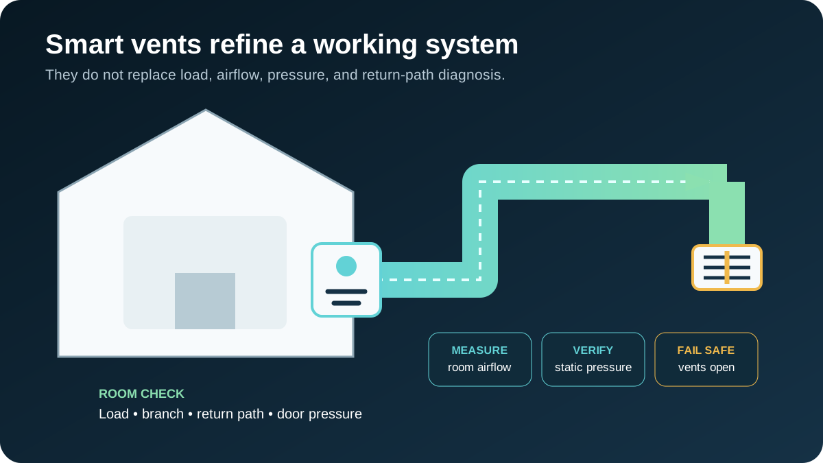
Short answer: A smart vent is not automatically safe or unsafe. It is a motorized supply register that changes resistance in a duct system. It may help trim airflow to a mildly overconditioned room when the underlying system has measured pressure headroom, enough open supply area, a proper return path, compatible equipment controls, and a fail-open response. It is a poor fix for undersized ducts, missing returns, high baseline static pressure, excessive equipment capacity, or a room whose load exceeds the branch's capacity.
Do not begin by buying registers. Begin by measuring the room and the system with every register open. The decisive evidence is room-by-room load and airflow, supply and return pressure, total external static pressure, equipment-required airflow, and temperature response. A product app cannot infer all of those from a temperature sensor.
What a Smart Vent Can and Cannot Do
A retrofit smart vent replaces a manually adjustable supply register. Its actuator opens or closes the register in response to a schedule, occupancy rule, room sensor, or central controller. Some systems also monitor duct pressure or limit the fraction of closed vents.
That mechanism can reduce airflow into one room. It cannot create additional blower capacity, enlarge a small branch, add a return path, repair a disconnected duct, lower solar gain, or make a single-stage system shrink its output. When one outlet closes, air may redistribute to other outlets, blower airflow may change, duct leakage may increase, or pressure may rise. Which result dominates depends on the fan, duct network, controls, and number of closed registers.
Use smart vents for fine control after commissioning, not as a diagnosis. A room that is eight degrees warmer than the rest of the house probably has more than a register-control problem.
Diagnose the Room Before You Restrict It
Comfort complaints fall into several categories, each with a different repair.
| Symptom | Likely questions | Smart vent relevance |
|---|---|---|
| Room is always too hot in heating and too cold in cooling | Is its supply airflow high relative to room load? | Possible trimming candidate |
| Room is too cold in heating and too hot in cooling | Is supply airflow low, the branch restricted, or room load high? | Closing another room may mask, not fix, the shortage |
| Problem appears only with door closed | Does the room have an adequate return-air path? | Fix return pressure first |
| Afternoon summer overheating | Is west-facing glass or roof gain dominant? | Shading or envelope work may be more effective |
| Large swing with short equipment cycles | Is the equipment oversized or thermostat poorly located? | Register control cannot reduce single-stage capacity |
| Weak airflow at every register | Is the filter, coil, return, or blower limiting total airflow? | Added restriction is inappropriate |
| One branch is noisy | Is the register undersized or branch velocity already high? | Throttling may increase noise |
Build a two-day comfort record
Record outdoor temperature, solar conditions, thermostat state, room temperatures, door position, occupancy, and equipment stage at consistent intervals. Note whether the room diverges during heating, cooling, or both. A small sensor at sitting height away from direct sun and supply air is more useful than an app sensor placed on a hot exterior wall.
The direction of the error is diagnostic. A room overconditioned in both seasons may receive too much airflow for its load. A room that is cold in winter but also cold in summer may have an envelope problem plus generous airflow. A room that changes only when its door closes points toward return-path pressure.
Measure Room Load and Delivered Airflow
The room-by-room portion of a Manual J load calculation estimates how much heating and cooling each room needs at design conditions. The distribution design then assigns airflow to meet those loads. Existing homes rarely retain a perfect design record, so field measurement matters.
Measure airflow at every supply with a balancing hood or another appropriate method, then sum registers by room. DOE's duct-retrofit guidance proposes comparing room airflow with room load as a balancing ratio. A room receiving much more CFM per unit of load than its peers is a defensible candidate for adjustment. A room receiving less needs a delivery or load solution, not a vent that closes elsewhere by guesswork.
A contractor should also inspect:
- crushed, kinked, disconnected, or excessively long flex duct;
- takeoff and manual balancing-damper positions;
- register and grille free area;
- duct leakage, especially outside conditioned space;
- coil and filter pressure drop;
- return grille and return-duct sizing;
- closed-door room pressure;
- thermostat location and equipment staging.
The duct leakage testing and sealing guide explains why a duct pressure test and a room airflow test answer different questions. Sealing a disconnected branch can restore more comfort than any control algorithm.
The Static-Pressure Test That Comes First
Static pressure is resistance to airflow. Total external static pressure is commonly measured on the return and supply sides of the air handler or furnace, outside the equipment sections defined by the manufacturer. The reading is paired with fan speed and the OEM blower table to estimate airflow, or airflow is measured with another accepted method.
ENERGY STAR's commissioning checklist records return external static pressure, supply external static pressure, total external static pressure, fan setting, and measured fan airflow. It also calls for comparing delivered airflow with design airflow. Those fields are a useful model for evaluating smart vents because an open-register baseline may already be near the equipment's limit.
Ask for measurements in at least these states:
- all supply registers fully open;
- the proposed maximum closure pattern;
- the smallest credible calling zone or occupied-room combination;
- high-stage heating and high-stage cooling where applicable;
- a fail-safe condition after loss of network or controller power.
Record the pressure on both sides, not just a single number from the supply plenum. If supply pressure rises while total airflow falls, the system is not safely “pushing the same air elsewhere.”
There is no universal safe closure percentage
Rules such as “never close more than 10%” or “keep one-third open” are screening shortcuts. Registers differ in size and free area; branches differ in resistance; equipment differs in fan response. Closing one large, low-resistance outlet may affect the system more than closing two small outlets at the end of long branches.
Define a minimum-open configuration from measured acceptance criteria. The smart-vent controller should never command a smaller open area than that configuration, even if every room sensor requests closure.
PSC and ECM Blowers Respond Differently
Older permanent split capacitor (PSC) blowers and electronically commutated motors (ECMs) do not respond identically to added resistance.
A PSC blower operating on a fixed speed tap generally moves less air as external static pressure increases. Lower airflow can reduce cooling performance, promote coil icing under some conditions, or push a furnace beyond its permitted temperature rise.
Many ECM systems attempt to maintain programmed airflow across part of their operating range by increasing speed and electrical input as resistance rises. That does not make them immune to restrictions. Every blower has an operating envelope. Beyond it, airflow may still fall, noise and watt draw may rise, and the control may reach its limit.
“Variable speed” also does not prove that the outdoor unit can reduce capacity enough for a tiny room. The indoor blower, compressor, furnace stages, thermostat, zone controller, and dampers must operate as a coordinated system. Request the actual model numbers and control sequence.
Temperature Rise, Coil Behavior, and Equipment Safeties
Airflow protects heat exchangers and coils as well as comfort.
For a furnace, the measured supply-to-return temperature rise must remain within the range on the equipment nameplate under the tested configuration. If vent closure pushes the rise above that range or triggers a high-limit control, reject the closure pattern and diagnose airflow.
For cooling, inadequate airflow can lower coil temperature and contribute to icing, especially when combined with low load, a dirty coil, low refrigerant charge, or control faults. Proper commissioning also considers refrigerant charge and manufacturer airflow targets. Repeated freeze-ups are not evidence that the smart vent needs a new schedule; they require service.
For a heat pump, test heating and cooling modes plus defrost-related behavior where conditions permit. Auxiliary heat staging can change required airflow and supply temperature. A smart-register system that behaves acceptably in low-stage cooling may fail its pressure or temperature limits during high-stage backup heat.
Return Air Is Half of the Room-Airflow Circuit
Supply air entering a bedroom needs a path back to the air handler. With the door closed, an inadequate return path pressurizes the room and can reduce supply delivery. The hallway or central return area may become negative. DOE Building America guidance describes dedicated returns, jump ducts, transfer grilles, and door undercuts as return-path options, while warning that door undercuts are often too small or blocked by carpet.
Measure room pressure relative to the main body of the house with the air handler operating and the door closed. If pressure is excessive under the applicable design standard, improve the return path before adding register automation. A transfer grille must also address sound and privacy; a lined or offset path may be preferable to a straight opening.
Smart vents on supplies do not solve a pressurized closed room. They may reduce the amount of air trying to enter, but that trades away conditioning rather than completing the circuit.
Manual Balancing Before Automated Balancing
Many duct systems include manual balancing dampers near branch takeoffs. These dampers are generally better for permanent balancing than closing a register at the room because they allow adjustment upstream and preserve the diffuser's throw pattern. They should be set using measured room airflow, not random lever positions.
Use this order:
- repair disconnected, damaged, or severely compressed ducts;
- clean or replace a restrictive filter and address a dirty coil;
- provide adequate return paths;
- confirm equipment airflow and fan settings;
- balance branches to room loads;
- correct high-gain envelope problems where practical;
- evaluate whether small, time-varying imbalances remain.
Only step seven is a strong smart-vent use case. The system then trims around a sound baseline rather than continuously compensating for a defect.
Retrofit Smart Vents Versus Designed Zoning
Retrofit smart registers and a professionally designed zoned system are not interchangeable.
| Feature | Retrofit smart registers | Designed duct zoning |
|---|---|---|
| Control point | Individual supply outlet | Zone dampers, usually upstream in branches or trunks |
| Equipment communication | Varies by product | Designed through thermostat/zone board/equipment sequence |
| Capacity response | Often indirect or absent | Can stage or modulate compatible equipment |
| Pressure management | Open-area rules or sensors vary | Designed and commissioned for worst-case zone |
| Best scale | Fine room trimming | Larger zones with known loads and airflows |
| Primary risk | Too much outlet closure without system coordination | Small zones, poor bypass strategy, or incompatible single-stage capacity |
For the design choices around zone dampers, variable capacity, relief strategies, and bypass ducts, use the separate HVAC zoning and bypass-damper guide. A bypass that routes supply air directly back to return can create low mixed-air temperatures in cooling or high return temperatures in heating, so it is not an automatic cure. Any bypass strategy needs manufacturer-compatible design and temperature verification.
A Smart-Vent Controls Specification
If measurements support a retrofit, require the system to document and enforce these controls:
Minimum open capacity
List the exact registers or total effective area that must stay open in each equipment stage. Use field-tested configurations, not a percentage copied from marketing material.
Pressure limit
If the product uses a pressure sensor, document its location, calibration, alert threshold, and response. A sensor in one branch does not necessarily represent total external static pressure at the equipment.
Equipment-state awareness
The controller should know whether the system is in fan-only, low or high cooling, heat-pump heating, furnace heating, or auxiliary heat. A closure acceptable at low airflow may be unacceptable at high airflow.
Fail-open behavior
Define what happens when batteries die, Wi-Fi fails, a hub reboots, a temperature sensor goes offline, or the cloud service is unavailable. Mechanical position and local control matter. “App unavailable” must not strand multiple registers closed during a heating call.
Conflicting-room logic
One room may ask for cooling while another is already cold. Document priority, deadband, maximum run time, and the minimum number of rooms that can call. Do not let one small office drive a full-capacity compressor indefinitely.
Manual override and removal
Occupants and service technicians need a clear way to open every register. Keep the original registers so the retrofit is reversible.
Commissioning and Acceptance Table
Run the proposed maximum-restriction scenario under each important equipment stage. Stop if equipment limits are exceeded or abnormal operation appears.
| Measurement | All open | Maximum planned closure | Acceptance source |
|---|---|---|---|
| Return external static pressure | OEM/design | ||
| Supply external static pressure | OEM/design | ||
| Total external static pressure | OEM blower data | ||
| Delivered blower airflow | OEM/design airflow | ||
| Furnace temperature rise | Nameplate range | ||
| Cooling/heat-pump operating checks | Manufacturer procedure | ||
| Blower watts | Baseline comparison | ||
| Airflow at each open register | Room load/balance report | ||
| Closed-door room pressure | Applicable design target | ||
| Sound in occupied rooms | Owner acceptance |
Repeat a subset after occupants have used the schedules for a week. Review event logs for persistent calls, repeated opening and closing, equipment limit trips, rooms that never recover, and batteries draining unusually fast.
A Worked Room-Control Example
Consider a two-storey house with one upstairs bedroom that runs cool during heating. The intuitive move is to close several downstairs registers. Testing finds a different story:
- the bedroom's design heating load is 4,500 Btu/h;
- measured supply airflow is low relative to peer rooms;
- the bedroom becomes positively pressurized when the door closes;
- the branch contains compressed flex duct;
- total system static pressure is already high with all registers open.
Smart vents downstairs would add resistance while the actual shortage remains. The repair sequence is to correct the flex duct, add or improve the return path, verify total airflow, and rebalance branches. If the room then tracks within a degree except during afternoon sun, a shade or small control adjustment may finish the job.
Now consider a dining room that is consistently overconditioned in heating and cooling. Its branch delivers substantially more airflow per unit of design load than comparable rooms; the return path is good; baseline static pressure is low; and testing shows that trimming this outlet keeps all equipment readings within limits. That is a more credible candidate for a manual damper adjustment or a smart register if the need varies by time and occupancy.
The distinction is measurable surplus versus assumed surplus.
Renters and Homes Without Permission to Modify Ducts
Renters should not alter registers, thermostat wiring, or equipment without owner approval. Safer reversible comfort steps include:
- keeping existing supplies and returns unobstructed;
- using permitted window coverings to reduce solar gain;
- checking whether a door position changes the problem;
- documenting temperatures and equipment runtime for the property manager;
- using a safe, appropriately sized fan to mix room air;
- requesting filter, duct, and HVAC service when airflow is visibly weak.
Do not use improvised magnetic covers on supplies or returns as a zoning system. They can create the same restriction without monitoring or fail-safe control.
What to Put in a Contractor Scope
Ask bidders to provide:
- room-by-room design loads or a defensible existing load analysis;
- measured supply airflow by room;
- closed-door room pressure results;
- baseline total external static pressure and blower airflow;
- the exact maximum-closure test configuration;
- readings for each relevant equipment stage;
- proposed return-path or duct corrections before controls;
- a written sequence of operation and fail-safe state;
- an owner handoff showing manual override and maintenance;
- post-installation readings and a balancing report.
If a contractor proposes a new zoned system rather than retrofit vents, request the smallest-zone load, required airflow, equipment minimum capacity, damper schedule, pressure strategy, and temperature-limit controls. “The zone board handles it” is not a design calculation.
Frequently Asked Questions
Will closing one vent damage my HVAC system?
Not necessarily. The effect depends on the outlet's size, branch resistance, baseline static pressure, fan response, and equipment airflow requirements. The cumulative configuration matters more than the count. Avoid casual closure and measure the proposed operating state.
Can smart vents save energy?
They may reduce conditioning delivered to selected rooms, but whole-system savings are not guaranteed. Higher pressure, duct leakage, extra blower power, longer runtime, or overconditioning elsewhere can offset the reduction. Measure energy and comfort against a weather-normalized baseline.
Do variable-speed systems make smart vents safe?
No label guarantees compatibility. A variable-speed blower may compensate for resistance, and a variable-capacity compressor may reduce output, but their operating ranges and control integration still need verification.
Should every bedroom have a return grille?
Not always. Dedicated returns, jump ducts, transfer grilles, and properly designed central-return pathways can work. The test is whether the closed room has an adequate, code-compliant return path with acceptable pressure, sound, privacy, and fire/smoke considerations.
Is a bypass damper required for zoning?
Not universally. The right approach depends on equipment capacity, minimum airflow, zone sizes, duct design, controls, and manufacturer requirements. Bypass ducts introduce their own temperature and efficiency concerns.
What is the simplest alternative to smart vents?
For a permanent imbalance, measure and adjust branch balancing dampers. For a sensor-location problem, a thermostat with remote sensors may improve comfort without restricting ducts. For a load problem, shading, air sealing, or insulation may address the cause.
The Decision Rule
Use a smart vent only when five statements are true:
- the room has measured excess airflow relative to its load or a legitimate time-varying need;
- the duct and return paths are sound;
- the all-open system meets airflow and pressure requirements;
- the maximum closure configuration also passes pressure, airflow, temperature, and noise checks in every relevant stage;
- loss of power, network, or sensors leaves the system in a safe state.
If any statement is false, repair or redesign first. Smart controls are most valuable when they refine a system that already works.
About the Editorial Team EnergyBS reviews public program rules, product specifications, utility rates, and reader-facing cost assumptions. Treat savings figures as estimates until you verify local prices, permits, rebates, and contractor quotes.
What to Read Next
The Myths of HVAC Zoning (2026 Guide & Data)Use this next to compare the cost, incentive, installation, or operating-risk angle before you make a home energy decision.Sources and Verification
Editorial Review
EnergyBS Editorial Team
EnergyBS publishes practical homeowner guides. Important program, product, and cost claims should be checked against the linked source and local project documents before you commit to work.
Related Guides
View All ArticlesThe Myths of HVAC Zoning (2026 Guide & Data)
Closing vents kills furnaces. Zone dampers increase static pressure. How to zone your home correctly without destroying equipment.
The Death of the SingleThermostat Home 2026 Tool
Heating a whole house when you're only in one room is a thermodynamic disaster. Discover how automated predictive modeling and thermal sensors are fixing the 'single thermostat' problem.
Duct Leakage Testing and Sealing: A Homeowner's Guide to DuctBlaster Results
A practical guide to total duct leakage, leakage to outdoors, CFM25 results, pressure problems, sealing materials, contractor scopes, safety checks, and postwork verification.